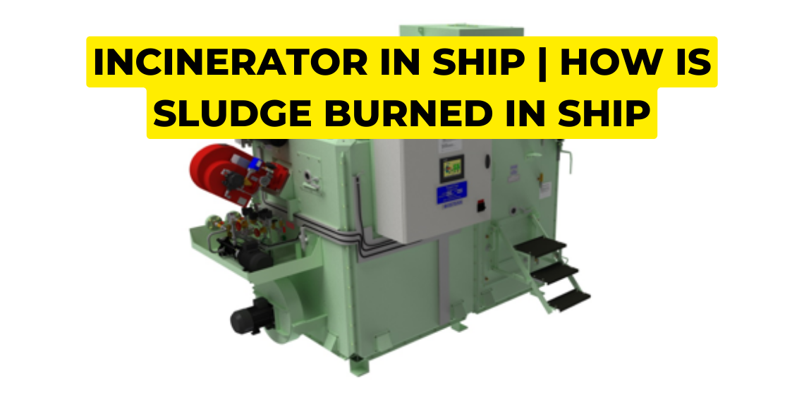
Incinerator in ship | How is sludge burned in ship | Constructions and Components of Incinerator |
An incinerator is a device used on board a ship to burn various types of waste, including sludge, paper, wood, soot, oily rags, and plastic (incinerator is specifically designed to burn plastic and is approved by the International Maritime Organization, IMO). The Incinerator is used to burn sludge (liquid) as well as Solid waste generated on the ship.
Under the MARPOL Convention, Annex V regulates the disposal of garbage from ships and establishes guidelines for various types of waste. The annex prohibits the dumping of several types of waste, including plastic, food waste, and paper, among others, into the sea to prevent marine pollution.
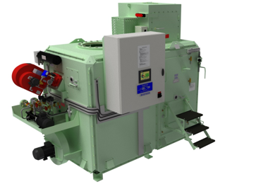
However, incineration of waste on board ships can help reduce the amount of waste that needs to be stored on board and minimize the risk of marine pollution. Therefore the use of Incinerators is an important waste management solution for ships. By burning waste, the volume of waste can be reduced, and the ash residue can be safely stored or disposed of. This can help prevent the discharge of harmful substances into the sea, protecting the marine environment.
Note: An Incinerator can also be a source of air pollution if not operated properly and if the emissions are not properly monitored and controlled.
Process of Burning Sludge in Incinerator
- Sludge generated from various sources on ships, such as lube oil sludge tanks and purifier sludge tanks, is typically transferred to the incinerator waste oil tank in the incinerator.
- Due to the presence of water in the sludge, it can be challenging to burn efficiently. To address this, steam is used to evaporate the water at high temperatures, which is then vented out through a vent pipe.
- The mercury-filled sensor is placed inside the incinerator waste oil tank to sense its temperature. The steam line temperature-controlled valve is mounted on the Steam line to regulate the flow of steam based on the temperature detected by the sensor.
- The resulting water-free sludge is then transferred directly from the incinerator waste oil tank to the incinerator for further burning.
Note: In some cases, fuel oil sludge and lube oil sludge are difficult to burn and require mixing to achieve proper burning.
Constructions and Components of Incinerator:
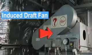
- Induced Draught fan: An ID fan is commonly used to suck the air from the furnace and create negative pressure inside the furnace which possess to introduced fresh air from the atmosphere. Fresh air is used for the burning process as well as for cooling the furnace. The basic components of an ID fan include an impeller fan, motor, drive mechanism (belt), and casing.
2. Incinerator Diesel oil tank: An incinerator diesel oil tank is a storage tank that is used to store diesel fuel for the burning process in Incinerator, the tank is typically located near the incinerator and is connected to the incinerator’s fuel supply system.
3. Pilot Burner Assembly: Pilot burner is located near the main burner, It consists of a nozzle, electrodes, and solenoid valve and it provides the initial flame required to ignite the waste on board the ship.
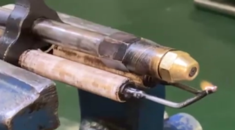
- Over these electrodes, 10,000 volts of voltage are generated and sparks are generated across a 3 mm to 5 mm gap between them.
- Through the nozzle, diesel oil is injected.
- Solenoid Valve is fitted over here to control the flow of air.
With the help of these three components, the initial ignitions take place.
4. Main Burner Assembly: Main Burner assembly is a critical component that is responsible for generating the high temperatures required to burn waste on board the ship. The main burner of the Incinerator is a type of Rotary cup burner. It consists of several components including a fan with motor and drive mechanism, a gear diesel oil pump, and a Solenoid valve (temperature controlled).
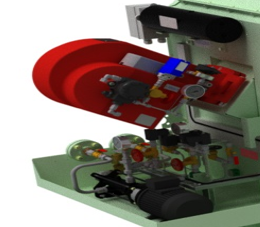
When the solenoid valve senses a temperature above 650 degrees Celsius, it allows the oil to flow into the furnace for burning the sludge at high temperatures.
5. Furnace Chamber: The furnace chamber is the main component of an incinerator where the waste is burned at a high temperature of about 800-1200 degrees Celsius. It is an enclosed space made up of high-resistance materials, such as refractory bricks or castable refractories.
6. Damper: The Damper is designed to maintain a consistent airflow through the incinerator. It is typically a moveable plate or valve that is mounted at the exhaust side and atmosphere side to control the rate of airflow and adjust the temperature of the exhaust gas by mixing them together.
Controls and Automation:-
Opening Alarm:
The opening alarm is a safety feature that alerts the operators that the door of the furnace is open so don’t fire the incinerator.
If a fire takes place inside the furnace with an open door then high-temperature gas or flame may come out and cause a fire inside the engine room.
Furnace Overheat Alarm:
When the furnace temperature increases above 1200 degrees Celsius then it will damage the refractory material and in that case, it trips the burner and the fuel supply cut off.
Furnace Temperature Low Alarm:
When the furnace temperature decreases, the moment when the temperature becomes 650 degrees celsius then the furnace temperature low alarm is raised and trips the incinerator because it may cause improper combustion and damage to the refractory.
Gas Overheat Alarm:
The maximum temperature for the exhaust gas leaving the furnace is 350 degrees Celsius. If the temperature exceeds this limit, then the alarm will raise and indicates some malfunction.
Draft Fault:
If the induced draft fan is not functioning or fails to generate a negative pressure inside the furnace, a draft fault alarm will activate. This alarm indicates that a vacuum has not been established within the furnace. Without the induced draft fan drawing air from the furnace, proper combustion cannot occur, and fresh air will not be introduced. To measure the vacuum pressure of the furnace, a furnace vacuum gauge is fitted. If the vacuum is not present inside the furnace, the alarm will raise.
Flame Eye:
The flame eye senses the flame inside the incinerator. The Photocell is fitted inside the flame eye which checks whether there is flame or not. If there is no flame, it will not send the waste oil inside the furnace and trip the main burner.
Note:
If you want to learn more about this topic, we suggest checking out our Combo package with the given link https://www.merchantnavydecoded.com/courses/c/ . It’s a great way to dive deeper into the subject through video explanations. This package covers all the important details and presents them in an easy-to-understand format. Watching the videos will help you grasp the topic better and make learning more enjoyable. So, we highly recommend giving our Combo package a try to enhance your knowledge on the subject.
Disclaimer :- The opinions expressed in this article belong solely to the author and may not necessarily reflect those of Merchant Navy Decoded. We cannot guarantee the accuracy of the information provided and disclaim any responsibility for it. Data and visuals used are sourced from publicly available information and may not be authenticated by any regulatory body. Reviews and comments appearing on our blogs represent the opinions of individuals and do not necessarily reflect the views of Merchant Navy Decoded. We are not responsible for any loss or damage resulting from reliance on these reviews or comments.
Reproduction, copying, sharing, or use of the article or images in any form is strictly prohibited without prior permission from both the author and Merchant Navy Decoded.



Excellent job ….